The requirement to study different topologies for a large number of nodes, imposes a system design and implementation which is highly modular and flexible while maintaining a very low cost per node. This has been achieved by building the testbed from three basic modules, which are packaged in VME mechanics:
Traffic Modules: A traffic node can simultaneously send and receive data at the full link speed of 100 Mbits/s. A series of packet descriptors is used to define the traffic pattern. The packet destination address, the packet length and the time to wait before dispatching the next packet is programmable. Each traffic node has memory for up to 8k such packet descriptors. To reduce the number of external connections, sixteen traffic nodes are connected directly to an on-board STC104 packet switch to form a traffic module. The remaining 16 ports of the switch are brought out to the front panel for inter module connections.
Switch Units: In order to build indirect networks, i.e. topologies where not all the switches have terminal nodes attached directly to them, a switch unit is required. It consists of one STC104 packet switch with all 32 ports brought out to the front panel through differential buffers.
Timing Modules: To measure latency, the timing modules transmit and analyse time stamped packets which cross the network between chosen points.
Further details on the design of the testbed have been presented in [].
Grid, torus and Clos [] network topologies have been studied. Figure 1 shows how a 400 node 2-dimensional grid network can be constructed. Each packet switch has 16 on-board connections to traffic nodes and four external connections to each of its four nearest neighbours.
A 256 node 3-stage folded Clos network is shown in figure 2. The centre stage of the Clos consists of the switch modules described above. Each terminal stage switch connects with groups of two links to every switch in the centre stage.
Grid style networks are easier to physically implement, since connections are all to adjacent switches, while Clos topologies have the constraint that each switch in the centre stage must be connected to every switch in the terminal stage.
The third topology which has been studied is the torus. A torus is similar to a grid which has its edge links wrapped around to connect to the opposite side of the network.
The STC104 supports a locally adaptive routing scheme which allows packets to be sent down any free output link in a programmed set of consecutive links. This improves performance by ensuring that there are no packets waiting to use one link when an equivalent link is idle. A set of links used to access a common destination can therefore be logically grouped together, increasing the aggregate throughput to the destination. This grouped adaptive routing allows efficient load-balancing in multi-stage networks [] and also enables a degree of automatic fault-tolerance []. On the grid topology, grouped adaptive routing is used on parallel links between adjacent routers. For Clos networks, all the links from the terminal stage switches to the centre stage can be grouped, because all the centre stage switches are equivalent. Parallel links from the centre stage to the terminal stage are also grouped.
The full scale system with 1024 nodes has been built and tested. A range of 2-dimensional grid, torus and multistage Clos networks have been assembled, results are presented for these configurations. Measurements to study other topologies such as hypercube networks are on-going.
- Throughput and comparison of network topologies
- Scalability of Clos and grid networks
- Network latency for Clos networks
- Effect of grouped adaptive routing
- Reliability
Figure 3 shows the per node saturation throughput for 2-dimensional grids, Clos and torus networks as a function of the packet length. The traffic pattern is random, i.e. transmitting nodes choose a destination from a uniform distribution.
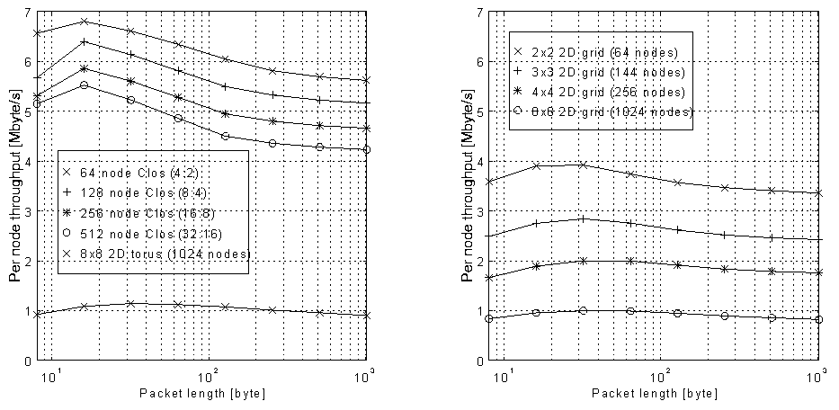
Figure 3: Per node throughput for 2-dimensional grid, torus and Clos networks under random traffic
The per-node throughput of the Clos networks is higher than for the 2-dimensional grids. This is because of the larger cross-sectional bandwidth, e.g. the 256 node Clos has a maximum theoretical cross-sectional bandwidth of 2.44Gbytes/s, whereas for the grid of the same size it is only 305Mbytes/s. The maximum cross-sectional bandwidth is defined as the bidirectional data rate that can pass between two parts of the network if it is divided into two equal halves. For the grid networks, the per-node throughput decreases rapidly as the network size increases, e.g. for a 1024 node grid, which consists of an array of 8 x 8 switches, the per node throughput under random traffic is only 10% of the maximum link bandwidth.
The results show that the network throughput under random traffic is always significantly lower than the maximum theoretical cross-sectional bandwidth. This is because the throughput of the network under random traffic is limited by head-of-line blocking. When several packets are contending for the same output link and a packet is stalled because the required output link is busy, all packets in the input queue behind it are also blocked, even if their selected output link is free. This effect limits the theoretical performance of a cross-bar switch under random traffic to about 60% of the maximum cross-sectional bandwidth [].
The effect of packet length on throughput can also be observed in Figure 3. For small packets of less than 16 bytes the throughput is reduced due to protocol overheads. Medium sized packets of around 64 bytes give the best performance because of the buffering present in the STC104: each switch can buffer 43 bytes in the input port, and 23 bytes in the output port. For the Clos network, long packets of more than 200 bytes fill the entire path through the network from source to destination, and therefore throughput is reduced by head-of-line blocking.
The throughput of the torus is about 20% higher than the grid due to the extra wrap around links which are available.
Figure 3 also shows that the throughput of Clos and 2-dimensional grid networks does not scale linearly with network size under random traffic, the per-node throughput is reduced as the network size increases. Figure 4 shows saturation network throughput for different sizes of Clos and 2-dimensional grid networks under random and systematic traffic for 64 byte packets. Systematic traffic involves fixed pairs of nodes sending to each other.
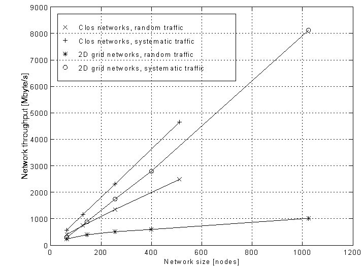
Figure 4: Throughput versus network size for Clos and grid networks under random and systematic traffic with 64 byte packets
For random traffic, contention at the destinations and internally to the network reduces the network throughput compared to that obtained for systematic traffic, where there is no contention or head-of-line blocking at the destination. The fall off in performance from systematic to random traffic is more pronounced for the grid than the Clos. The degradation of performance as the network size increases agrees with analytical models presented in []. This study predicts the throughput of Clos networks under sustained random load to degrade by approximately 25% from linear when the network size is increased from 64 to 512 nodes. The measurement results shown in Figure 4 show a reduction of about 20% under the same conditions.
The performance of the grid is strongly dependant upon the choice of pairs for systematic traffic. The results shown for the grid in Figure 4 use a 'best case' scenario, this traffic pattern involves communication between nodes attached to nearest neighbour switches. A 'worst case' scenario would be the pairing of nodes with their mirror image node in the network. The throughput of a 256 node grid under this 'worst case' pattern is 200Mbytes/s, as opposed to 1.8 Gbytes/s under the 'best case' pattern. This shows that on the grid, good performance requires locality. The throughput of the Clos under systematic traffic is independent of the choice of pairs due to its high cross-sectional bandwidth.
Network latency is defined as the delay from the transmission of the packet header at the source to the reception of the end-of-packet at the destination. Figure 5 shows the latency of four different size Clos networks under random traffic as a function of the aggregate network throughput. The packet length is 64 bytes. The results are produced by varying the network load and measuring the corresponding throughput and latency values. It can be seen that the average latency increases exponentially as the network throughput approaches saturation.
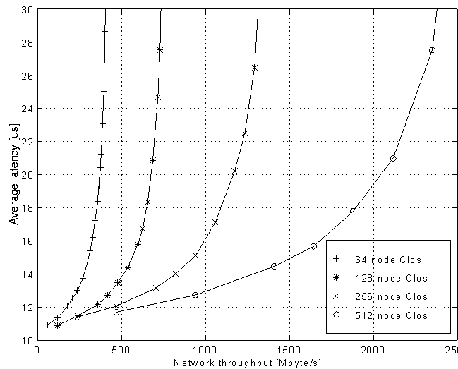
Figure 5: Latency versus throughput for Clos networks under random traffic with 64 byte packets
Some applications, e.g. multimedia traffic, may require statistical bounds on the maximum latency values occurring. This information can be obtained from Figure 6 which shows the probability that a packet will be delayed by more than a given latency value for various network loads. The results have been obtained on a 256 node Clos network. Again the traffic pattern is random, with a packet length of 64 bytes. From Figure 5 it can be seen that this network saturates at 1.35 Gbytes/s which corresponds to a load of 57%.
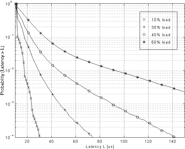
Figure 6: Cumulative latency distribution for a 256 node Clos network under random traffic with 64 byte packets
For 10% load the cumulative latency distribution is very narrow and only a small percentage of the packets (0.01%) are delayed by more than 3 times the average latency value of about 11 m s. As the network load increases, the tail of the latency distribution gets wider and near the saturation throughput a significant fraction of the packets experience a latency many times the average value, e.g. at 50% load 0.7% of the packets are delayed by more than five times the average latency of 21 m s. To reduce the probability of very large latency values the network load must therefore be kept well below the saturation throughput.
All the measurements presented so far have been made using grouped adaptive routing. In order to quantify the impact of this feature of the STC104 packet switch, deterministic routing and grouped adaptive routing have been compared on the Clos topology. With deterministic routing, routing channels are evenly spread across the centre stage links. Figure 7 shows the average network latency versus network throughput for a 256 node 3-stage Clos network under random traffic with 64 byte packets. The network load was increased until saturation occurred. Using grouped adaptive routing results in a nearly 20% higher saturation network throughput as well as lower average latencies. This is because the adaptive routing technique minimises the effects of load imbalance, thereby allowing a better utilisation of the links to the centre stage of the Clos network.
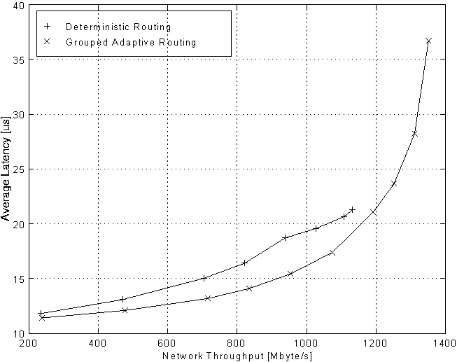
Figure 7: Deterministic and grouped adaptive routing on a 256 node Clos network under random traffic
We have tested differential DS-Link connections over twisted-pair cable for immunity against electromagnetic interference according to the IEC 801-4 standard []. The setup passed test severity level 2, which corresponds to the environment likely to be found in the control room of an industrial or electrical plant. We have also attempted to quantify the reliability of DS-Link systems using the 1024 node 8 x 8grid network by performing long-term error tests. The 1024 node grid contains a total of 1344 active DS-Links, about one third of these link use differential buffers and 2 meter twisted pair cables. The others are single-ended on-board connections. We have run the system continuously for over 200 hours without observing any link errors. This translates to a per-link error rate of better than 9.6·10-18.