4.0 S-LINK Usage Instructions
The simplex and duplex versions of the S-LINK can be switched to test mode by holding the UTEST# signal low. This causes the LSC to illuminate a test-mode LED and to transmit a fixed pattern to the LDC. The pattern commences with all zeros transmitted on the data lines and with LCTRL# set low. It continues with a walking bit pattern where a single bit is transmitted first on bit 0, then on bit 1 and so on with each data line in succession. LCTRL# is set high. This is effectively a bit shift left on each successive word. The test pattern is shown in Table 9 (in the example shown, the data width is assumed to be 32-bit and so the cycle repeats after 33 words). If an S-LINK is in 8-bit or 16-bit data width, the cycle repeats after 9 or 17 words. At the LDC, a test-mode LED is illuminated and the LDC checks the incoming data stream. If any pattern or transmission errors are detected the data error LED on the LDC is illuminated.
TABLE 9. Test pattern (for an S-LINK in 32-bit data width)
| Word | Hex value | Binary value | LCTRL# |
| 0 | 0x0 | 00000000000000000000000000000000 | 0 |
| 1 | 0x1 | 00000000000000000000000000000001 | 1 |
| 2 | 0x2 | 00000000000000000000000000000010 | 1 |
| 3 | 0x4 | 00000000000000000000000000000100 | 1 |
| 4 | 0x8 | 00000000000000000000000000001000 | 1 |
| 5 | 0x10 | 00000000000000000000000000010000 | 1 |
| --- | --- | --- | 1 |
| 29 | 0x10000000 | 00010000000000000000000000000000 | 1 |
| 30 | 0x20000000 | 00100000000000000000000000000000 | 1 |
| 31 | 0x40000000 | 01000000000000000000000000000000 | 1 |
| 32 | 0x80000000 | 10000000000000000000000000000000 | 1 |
| --- | --- | cycle repeats until test mode is ended | --- |
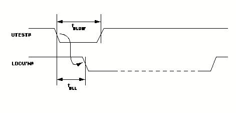
A timing diagram for the signals at the LSC is shown in Figure 5 and their values are given in Table 10. UTEST# may be pulsed low, in which case one test pattern cycle will be transmitted, or it may be held low for as long as required in which case the test pattern will be transmitted continuously. When UTEST# is set high to end the test, the S-LINK will remain in test mode until the current test pattern has finished transmitting. The maximum time for this is implementation dependent.
FIGURE 5. Test mode at the LSC
TABLE 10. Test Mode Timing Parameters
| Symbol | Description | Min | Max | Unit |
| tULL | UTEST# low to LDOWN# low | 4 | Cycles of UCLK | |
| tULOW | Minimum time for UTEST# low | 4 | Cycles of UCLK |
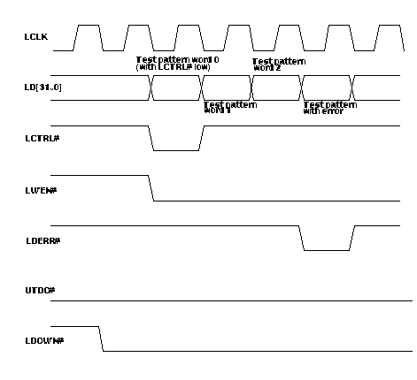
Note that the default state is that the test data is not transferred to the ROMB (LWEN# is high). If desired, the ROMB can receive the test pattern by setting UTDO# low. When this is done, the test pattern is presented on the data lines, LD[31..0] and on LCTRL#. Any errors are reported as described in Section 4.5. A timing diagram is shown in Figure 6. In this diagram, LWEN# is shown to be constantly low so that a new word is transferred on each clock cycle. This is actually implementation dependent and LWEN# may be high on some clock cycles if new data words are not ready.
In a duplex S-LINK, UXOFF# functions in test mode. That is, if UTDO# is low and the test pattern is being transferred to the ROMB, setting UXOFF# low will cause the LSC to stop sending the test pattern. When UXOFF# goes high again, the test pattern transmission will resume. If UTDO# is high, UXOFF# has no effect on test pattern transmission. When test mode is ended, the LSC continues to transmit test words until the current cycle has completed.
Switching an S-LINK to test mode clears any error latches which may have been set during normal data transfer and clears any data which may be waiting for transmission. Similarly, when test mode is ended, any error latches set during test mode are cleared. This includes the data error LED. In addition, any data which might be in a buffer is cleared on leaving test mode. This is shown in Table 11.
TABLE 11. Clearing of error latches on entering and leaving test mode
| Data Transfer Mode
|
| Switch to test mode - Clear errors here and clear any data buffers |
| Test Mode - block 1 Test Mode - block 2 ... Test Mode block N |
| Leave test mode - Clear errors here and clear any data buffers |
| Data Transfer Mode
|
From the user's point-of-view, the test mode has the same functionality in both the simplex and duplex versions of the S-LINK. However, in the duplex version the return physical link is also tested. An error in either physical link causes the data error LED on the LDC to be illuminated and latched.
Note that the return lines continue to function during test mode. That is, changes of state on lines URL[3..0] will be recognised and transmitted back to LRL[3..0] as described in Section 4.7.
LDOWN# is set low during test mode. This means that the FEMB shall not try to transfer data to the LSC during test mode.
FIGURE 6. Test mode at the LDC when UTDO# is set low