The HIPPI is a simplex channel, capable of transferring data in one direction only. Two HIPPI channels may be used to implement a full-duplex channel. The HIPPI is a point-to-point channel that does not support multi-drop. The point-to-point limitation considerably simplified the electrical and protocol aspects of the HIPPI. Crossbar switches and other networking methods are being considered to achieve the equivalent of multi-drop. An addressing mechanism is included to support these networking concepts.
The HIPPI provides support for low-latency, real-time, and variable-size packet transfers. The signal sequences provide look-ahead flow control to allow the average data rate to approach the peak data rate, even over distances of tens of kilometres. This is a benefit for future, fibre-optic versions of the HIPPI. Data transfers and flow control are performed in increments of bursts, with each burst nominally containing 256 words (1024 or 2048 bytes).
Error detection, but not error correction, is provided by the HIPPI. Byte parity is used on the data bus. In addition, each burst of data is immediately followed by a length/longitudinal redundancy checkword (LLRC). It is envisioned that error recovery would be done at a higher-layer protocol. Driving a video frame buffer, for example, is best served by ignoring errors that the next frame overwrites anyway.
Return to the begin of Introduction to the HIPPI Specification

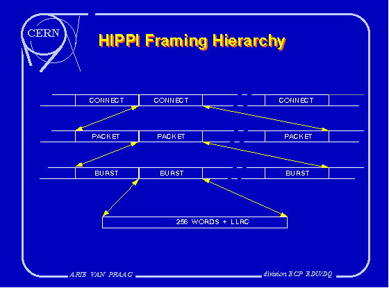
Figure 2: framing hierarchy of the HIPPI.
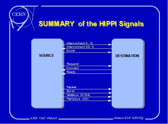
The interface signals are illustrated in Figure 3. The numbers in parentheses indicate the number of signal lines when using the 1600 Mbit/s option. The other numbers indicate the number of signal lines when

Figure 3: summary of the HIPPI signals. The numbers indicate the number
of signal lines when using the 800 Mbit/s (1600 Mbit/s) option.
using the 800 Mbit/s option. All signals, except for the INTERCONNECT signals, use differential emitter- coupled logic (ECL) drivers and receivers. The INTERCONNECT signals use single-ended ECL drivers and receivers.
Fifty-pair, twisted-pair cables are used for distances up to 25 meters. The 800 Mbit/s option uses one cable, and the 1600 Mbit/s option uses two cables. All of the signal lines in the HIPPI are unidirectional to accommodate future, fibre-optic implementations and crossbar switches. All of the control and data signals are timed in relation to the constant 25 MHz CLOCK signal with a period of 40 nanoseconds.
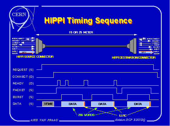
Typical HIPPI waveforms are shown in figure 4 for a sequence that establishes a connection, sends a packet containing three bursts of which the last one is a short one, sends a packet containing one burst, and then disconnects. A connection is made from the source to the destination much like a telephone connection. The source supplies the I-Field on the data bus (like a telephone number), and asserts the REQUEST signal. If the destination wants to accept the connection, it asserts the CONNECT signal. Although the contents of the I-Field are not specified in the HIPPI standard, the I-Field is intended for addressing or other control operations.

Figure 4: typical HIPPI waveforms.
If the destination does not want to accept the connection request from the source, it has two options: it either does not react at all, keeping the CONNECT line deasserted, or it can give a connection reject cycle. In the latter case, it will assert the CONNECT signal for 4 to 16 clock cycles, which will signal the source that the destination does not want to make a connection and therefore it can release the channel immediately.
Once a connection is established, single or multiple packets may be transferred from the source to the destination. Packets are delimited by the PACKET signal being true. Packets are composed of one or more bursts.
Bursts are delimited by the BURST signal being true. Bursts consist of a group of words sent on the data bus, one word per clock period, during contiguous clock periods. Bursts contain one to 256 words. Bursts that contain less than 256 words are called short bursts. There can be only one short burst per packet, and it must be either the first or last burst of the packet. Short bursts can be used for applications like packet headers, variable-length data transfers, and short messages that must be acted on quickly.
The LLRC checkword is sent from the source to the destination on the data bus during the first clock period following the burst. This Length/Longitudinal Redundancy Check checkword implements a longitudinal parity of all datawords in the burst and the lengthcount of the burst. The error detection mechanism provided by the LLRC and byte parity may be inadequate for certain applications because it does not detect certain 4-bit and 8-bit errors within a burst.
The destination controls the flow of data by issuing a READY pulse for each burst that it is prepared to accept from the source. If the READY pulses arrive at the source before the source is ready to send the next burst, there will be no time lost between bursts. Hence, the flow control is distance independent if the cable- length time is shorter than the time required to transmit the number of bursts. This requires about one burst buffer for each kilometre of cable distance.
The INTERCONNECT signals indicate to both the source and destination that the cable(s) are connected and that the other end is powered up. They may also be used to indicate whether the 800 Mbit/s or the 1600 Mbit/s HIPPI option is in use.
Return to the begin of Introduction to the HIPPI Specification
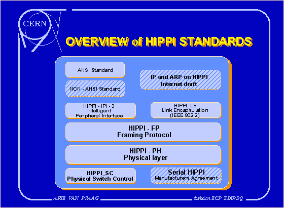
Figure 5 gives an overview of the logical connection of the current proposed HIPPI standards and other related documents.

Figure 5: overview of HIPPI standards and other related documents.
The HIPPI-PH standard is the description of the physical layer of a HIPPI interface. It also describes the service interface primitives to the upper layer protocols and to the station management. However, it must be noted that the description of the relation of the service primitives to the physical interface signals is not clear and even contains errors.
Return to the begin of Introduction to the HIPPI Specification
Currently there are three standards defined that interface to the HIPPI-FP layer. The first standard that connects to the FP-standard is the Link Encapsulation (HIPPI-LE, that specifies an encapsulation of IEEE 802.2 (ISO 8802-2) Logical Link Protocol Data Units in HIPPI-FP packets. The LE-standard defines the contents of the D1_Area and D2_Area of the FP-standard, but does not define the contents of the CCI.
The second standard is the IPI-3 document. This document describes the mapping between IPI-3 command sets and HIPPI-FP packets. This document will probably not become a separate standard but will be included in the IPI-3 Disk and IPI-3 Tape standards. The IPI-3 Disk and Tape standards define a device generic command set for storage devices.
The last standard connecting to the FP-standard being worked out by the X3T9.3 committee, is a generic memory interface protocol specification, called HIPPI-MI. This specification implements remote memory reads and writes over a HIPPI interface.
Return to the begin of Introduction to the HIPPI Specification
Furthermore, the ANSI X3T9.3 committee has drafted a proposal for the encapsulation of IEEE 802.2 LLC PDUs and, by implication, IP on HIPPI. This document discusses methods of using of ANSI standard HIPPI hardware and protocols in the context of the Internet, including the use of HIPPI switches as LANs and interoperation with other networks. This hippilan memo is intended to become an Internet Standard.
Return to the begin of Introduction to the HIPPI Specification
Return to the begin of Introduction to the HIPPI Specification
Return to the begin of Introduction to the HIPPI Specification
Return to the begin of Introduction to the HIPPI Specification