4.0 S-LINK Usage Instructions
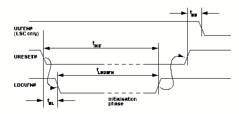
At the LDC, a similar procedure is followed: The ROMB sets URESET# low and the LDC responds by setting LDOWN# low and then initialising. When initialisation is complete, the LDC sets LDOWN# high.
If URESET# is set low on either S-LINK card, this should cause LDOWN# to be set low on the other S-LINK card. The other card will then have to be reset to clear LDOWN#.
This procedure is shown in Figure 7 and the values of the timing parameters are given in Table 12.
For a duplex S-LINK, the LSC and LDC can be reset in any order. For a simplex S-LINK, the LDC shall be reset first.
FIGURE 7. Reset procedure at the LSC and LDC
TABLE 12. Reset Cycle Timing Parameters
| Symbol | Description | Min | Max | Units |
| tRL | URESET# low to LDOWN# low | 4 | Cycles of UCLK or LCLK | |
| tRU | URESET# high to UWEN# low | 4 | Cycles of UCLK or LCLK | |
| tINIT | URESET# low to LDOWN# high | 15 | seconds | |
| tLDOWN | LDOWN# low duration | 4 | Cycles of UCLK or LCLK |