SLIDAD User's Guide
LSC-D-0/40-B/W-5.0-160
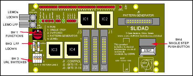
 Picture of SLIDAD. Photo of SLIDAD
CONTENTS
Introduction
The SLIDAD is a device that helps the designer of a Front-end Motherboard
(FEMB) during the debugging process of the S-LINK interface hardware. It
emulates the function of the Link Source Card by receiving the data as
if it was sent to a real S-LINK. With the help of a SLITEST,
the SLIDAD may also be used to test links and to receive data from a FEMB
via an S-LINK.
With the SLIDAD it is possible to receive data withouth having to set
up a real S-LINK. The device does not require any software, as you may
set all parameters with switches.
Operating modes
The SLIDAD has five operating modes which can be set with the rotary switch
SW1. This switch determines the source of the LFF (link full flag), LDOWN
(link down) and URL (return line) signals.
Although the switch has ten positions, only five positions are actually
used.
Table 1: Operating mode switch SW1
|
Position
|
Name
|
LFF# signal
|
LDOWN# signal
|
URL Return lines
|
| 0 |
Run |
1 (not full) |
1 (link up) |
sliding switches SW3 |
| 1 |
Single step |
0 after receiving one word, 1 after pressing pushbutton |
1 (link up). 0 after receiving URESET# asserted. 1 after pressing pushbutton |
sliding switches SW3 |
| 2 |
Switches |
sliding switch SW2a |
sliding switch SW2b |
sliding switches SW3 |
| 3 |
Pattern Generator |
J5, pin 11 |
J5, pin 9 |
J5, pins 1, 3, 5, 7 |
| 4 |
LEMOs |
Lemo LM2 |
Lemo LM1 |
sliding switches SW3 |
The position 'Run' is the default value. In this position the board will
accept any data and display it on the LEDs.
In the 'Single step' mode the board will accept a single word, after
which it will assert the LFF# signal, signalling that the link is full.
According to the S-LINK specification, the FEMB may still send two words
after the assertion of LFF#. If the FEMB indeed sends extra words after
the assertion of LFF#, the SLIDAD will accept those words. I.e. depending
on the implementation of the FEMB the SLIDAD is connected to, after pressing
the single step pushbutton, one or two words will be received. Only the
last word received will be displayed on the LEDs. This might be confusing
as you may think that some words are missing. To see all words, you may
want to connect a logic state analyser to the SLIDAD.
In the position 'Switches', all signals output from the SLIDAD are directly
taken from the sliding switches.
With the position 'Pattern Generator' all signals output from the SLIDAD
are directly taken from the pattern generator connector.
In the position 'LEMOs', the LFF and LDOWN signals are both taken from
the LEMO connectors at the front-panel. This position can be helpful if
you want to emulate flow control with a pulse generator connected to LFF
LEMO connector.
Step Push button (SW4)
The Step push button is used only in the "Single Step" operating mode.
It is both active on the LFF# signal as on the LDOWN# signal. Please see
the Operating Modes section.
Sliding switches (SW2, SW3)
The two switches marked SW2 are only active in the "Switches" operating
mode. When they are in the 'down' position (slider directed to text SW3),
the signals are inactive. I.e. LFF# signals the link is not full and LDOWN#
signals that the link is up. The actual values of LFF# and LDOWN# are also
reflected on the respective LEDs.
The four switches marked SW3 are active in all operating modes except
"Pattern Generator". These switches set the values of the link return lines
LRL[3:0]. When they are in the 'down' position (slider directed to text
"3 2 0"), the LRL signals have the 0 level. The actual value is also reflected
on the LRL LEDs.
LEDs
The state of all S-LINK signals are shown on LEDs. All LEDs are on when
the signal is active.
Table 2: SLIDAD LEDs
| Name |
On when |
Meaning |
| Power |
Vcc on |
Board is powered |
| LDOWN |
LDOWN#=0 |
Link is down |
| LFF |
LFF#=0 |
Link is full |
| TEST |
UTEST#=0 |
Test mode is on |
| RESET |
URESET#=0 |
Reset is active. Normally URESET# signal
is active only for a very short time, which
can make it not visible. |
| DW[1:0] |
UDW[1:0]=1 |
User data width. e.g. 00 is 32 bits |
| CLOCK |
UCLK=1
normally LED should be half-lit' |
User clock is active |
| LRL[3:0] |
LRL[3:0]=1 |
User Return Lines |
| D[31:0] |
D[31:0]=1
value of last dataword written |
Data lines |
| CNTL |
LCTRL#=0 |
Control word is received |
LEMO connectors (LM1, LM2)
The LEMO connectors are used only in the 'LEMOS' operating mode and are
an input to the LFF# and LDOWN# signals.
These inputs require TTL levels. They are not terminated and an open
input will make the signal levels undefined.
Logic state analyser connectors (J1-J3)
There are three logic state analyzer connectors on the SLIBOX that are
wired up directly to the S-LINK signals. The layout of the connectors is
made for an Hewlett Packard 16500 Logic State Analyser with an 100 KOhm
Termination Adapter (HP part number 01650-63203). Pre-made setups for making
state and timing analysis on S-LINK can be obtained from Erik
van der Bij. These files also contain complicated setups that can trigger
on missing words or too many words received.
Table 3: SLIDAD Logic State Analyser connectors
signal assignment
| J3: Bits 31..16 |
J2: Bits 15..0 |
J1: Control |
| Signal |
Pin |
|
Pin |
Signal |
| nc |
1 |
|
2 |
nc |
| nc |
3 |
|
4 |
UD[31] |
| UD[30] |
5 |
|
6 |
UD[29] |
| UD[28] |
7 |
|
8 |
UD[27] |
| UD[26] |
9 |
|
10 |
UD[25] |
| UD[24] |
11 |
|
12 |
UD[23] |
| UD[22] |
13 |
|
14 |
UD[21] |
| UD[20] |
15 |
|
16 |
UD[19] |
| UD[18] |
17 |
|
18 |
UD[17] |
| UD[16] |
19 |
|
20 |
Ground |
nc) not connected |
| Signal |
Pin |
|
Pin |
Signal |
| nc |
1 |
|
2 |
nc |
| nc |
3 |
|
4 |
UD[15] |
| UD[14] |
5 |
|
6 |
UD[13] |
| UD[12] |
7 |
|
8 |
UD[11] |
| UD[10] |
9 |
|
10 |
UD[9] |
| UD[8] |
11 |
|
12 |
UD[7] |
| UD[6] |
13 |
|
14 |
UD[5] |
| UD[4] |
15 |
|
16 |
UD[3] |
| UD[2] |
17 |
|
18 |
UD[1] |
| UD[0] |
19 |
|
20 |
Ground |
|
| Signal |
Pin |
|
Pin |
Signal |
| nc |
1 |
|
2 |
nc |
| UCLK |
3 |
|
4 |
nc |
| UCLK |
5 |
|
6 |
nc |
| Vcc |
7 |
|
8 |
LFF# |
| LDOWN# |
9 |
|
10 |
URESET# |
| UTEST# |
11 |
|
12 |
UWEN# |
| UCTLR# |
13 |
|
14 |
UDW[1] |
| UDW[0] |
15 |
|
16 |
LRL[3] |
| LRL[2] |
17 |
|
18 |
LRL[1] |
| LRL[0] |
19 |
|
20 |
Ground |
|
Pattern generator connector (J5)
The Pattern Generator connector J5 is used only in the 'Pattern Generator'
operating mode. In this operating mode the LFF#, LDOWN# and Link Return
Line signals are taken from the pins J5.
These inputs require TTL levels. They are not terminated and an open
input will make the signal levels undefined.
Table 4: SLIDAD Pattern Generator connector signal assignment
| Signal |
Pin |
|
Pin |
Signal |
| LRL0 |
1 |
|
2 |
Ground |
| LRL1 |
3 |
|
4 |
Ground |
| LRL2 |
5 |
|
6 |
Ground |
| LRL3 |
7 |
|
8 |
Ground |
| LDOWN# |
9 |
|
10 |
Ground |
| LFF# |
11 |
|
12 |
Ground |
| nc |
13 |
|
14 |
Ground |
| nc |
15 |
|
16 |
Ground |
| nc |
17 |
|
18 |
Ground |
| nc |
19 |
|
20 |
Ground |
nc) not connected |
RESET
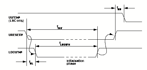
In the 'RUN' operating mode, the SLIDAD complies to the S-LINK reset protocol.
After it receives an asserted URESET# signal, LDOWN# will be asserted for
six cycles of UCLK.
In the "Single Step" mode, after having received URESET# asserted, LDOWN#
will get asserted, but won't deassert until the Step push button is pressed.
In all other operating modes LDOWN# is set directly from the external inputs
or the sliding switches.
The reset signal does not reset the SLIDAD itself. E.g. the data LEDs
will still show the last dataword that the SLIDAD received.

Figure 1: S-LINK reset protocol.
CERN - High Speed Interconnect
- S-LINK
Erik van der Bij
- 17 March 1998 - Copyright


