Communication benchmarks with the Ancor Fibre Channel Fabric
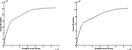
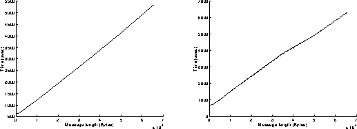
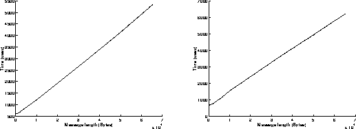
Figure 3a: (left) sender is 250, receiver is 590. (right) sender is 590, receiver is 250.

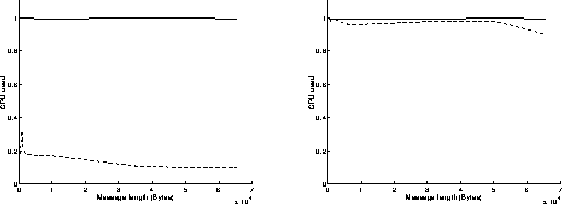
Figure 3b: (left) sender is 250, receiver is 590. (right) sender is 590, receiver is 250.
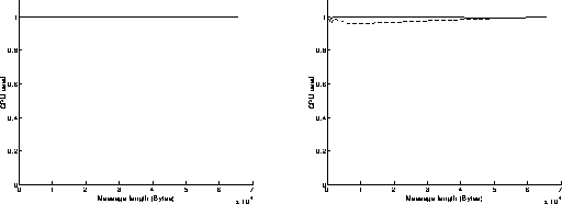
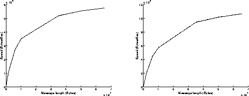
Figure 3c: (left) sender is 250, receiver is 590. (right) sender is 590, receiver is 250.
Figure 4a: (left) sender is 250, receiver is 590. (right) sender is 590, receiver is 250.
Figure 4b: (left) sender is 250, receiver is 590. (right) sender is 590, receiver is 250.
Figure 4c: (left) sender is 250, receiver is 590. (right) sender is 590, receiver is 250.
Figure 5a: (left) sender is 250, receiver is 590. (right) sender is 590, receiver is 250.
Figure 5b: (left) sender is 250, receiver is 590. (right) sender is 590, receiver is 250.
Figure 5c: (left) sender is 250, receiver is 590. (right) sender is 590, receiver is 250.
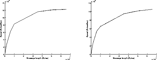
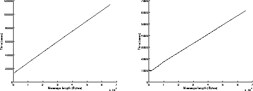
Figure 6a: (left) sender is 250, receiver is 590. (right) sender is 590, receiver is 250.
Figure 6b: (left) sender is 250, receiver is 590. (right) sender is 590, receiver is 250.
Figure 6c: (left) sender is 250, receiver is 590. (right) sender is 590, receiver is 250.
Let us just recall that our application is aimed at implementing the second level trigger according to a processor farm-based approach, each processor being connected to one or several Fibre Channel Fabrics, according to our requirements. In this case, each processor is really expected to do some processing task interleaving with communications. The results we present in this note are only related to communication performances, and therefore represent maximum values which never will be reached when implementing a parallel application in which some processing tasks will interleave the communication processes.
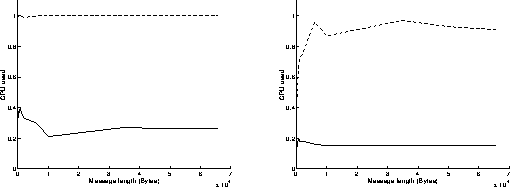
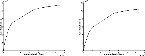
On figures 3, results have been achieved when using the Read and Write functions in a non blocking mode. The best performances are obtained when the most powerful workstation is receiving data (left graphs on figures 3). We can infer that the execution of the Read function is slower than the one of the Write function when using non blocking mode. Under these conditions, the overhead of the system is around 615 microseconds, and the speed can reach 12.2 MBytes/s for transmitting 65500 byte messages.
The ratio between the CPU time and the communication time is around 100 percent. This is due to the nature of the algorithm: the Write and Read functions are executed in an endless loop. On the sender side, even if the buffer is full, the Write function will continue on attempting to send some data and will return an error message (overflow), until some free space will be available in the buffer. That explains why the processor is always busy.The same problem occurs on the receiver side.
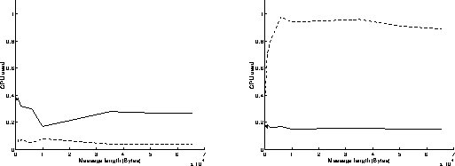
On figures 4, results have been achieved when using the Read function in a blocking mode and the Write function in a non blocking mode. As previously, the best performances are obtained when the most powerful workstation is receiving data (left graphs on figures 4). The results are similar to those obtained on figures 3: the execution of the Read function in a blocking mode takes indeed the same time as if it was achieved in a non blocking mode. Under these conditions, the overhead of the system is around 615 microseconds, and the speed can reach 12.2 MBytes/s for transmitting 65500 byte messages. On the left graph of figure 4c, we can see that the percentage of CPU time used at the receiver side is below 20 percent: that means that the receiver is sustaining the data flow without any problem and must often wait for data to come in.
On figures 5, results have been achieved when using the Read function in a non blocking mode and the Write function in a blocking mode. Now, the execution of the Write function takes a longer time than the one of the Read function, because it has to wait for an acknowledgment before returning. This explains why the best performances are obtained when the most powerful workstation is sending data (right graphs on figures 5). Under these conditions, the overhead of the system is around 1 millisecond, and the speed can reach 10.6 MBytes/s for transmitting 65500 byte messages.
On figures 6, results have been achieved when using the Read and Write functions in a blocking mode. As previously, the best performances are obtained when the most powerful workstation is sending data (right graphs on figures 6). The results are similar to those obtained on figures 5: the execution of the Read function in a blocking mode takes indeed less time than the execution of the Write function in a blocking mode. Under these conditions, the overhead of the system is around 1 millisecond, and the speed can reach 10.5 MBytes/s for transmitting 65500 byte messages.
Generated with WebMaker
Write in a non blocking mode, Read in a blocking mode
Write in a blocking mode, Read in a non blocking mode
Read/Write in a blocking mode

Conclusion
Fabrice Chantemargue - 30 AUG 94
[Next] [Prev] [Top]