4.0 S-LINK Usage Instructions
If the ROMB reaches a state in which it cannot process new data words coming from the LDC, it can stop the flow of data by setting the line UXOFF# low. This causes the LDC to send an XOFF command back to the LSC which forces it to stop transmitting data. If the LSC has a buffer memory the LSC may still receive transfers from the FEMB but eventually the buffer will fill and this will cause LFF# to be set low. This data is not lost but is simply stored until UXOFF# goes high and data transmission resumes.
The user should be aware that transfers from the LDC to the ROMB will not stop immediately when UXOFF# is set low. There is a latency which is the sum of the reaction time of the LDC (to transmit an XOFF code to the LSC), the transmission time of the XOFF code to the LSC, the reaction time of the LSC (to stop transmitting data), and the transmission time of the last data word from the LSC. This could be quite large, for example, in the case of an S-LINK which transfers data words on a 20 ns cycle over a 200 m link, more than 100 words could be transferred from the LDC to the ROMB after UXOFF# is set low. The user should calculate this latency for the implementation in use and ensure that when the ROMB asserts UXOFF#, it still has sufficient capacity to receive latent transfers.
Equation 1 shows how to calculate the ROMB buffer size required for any particular implementation. Note that if a ROMB designed for one implementation is used in another which has different parameters (such as a longer transmission length) the flow control mechanism may not work.
Where:
RBS = ROMB Buffer Size (words)
LDCrt = LDC reaction time to send XOFF after UXOFF# goes low (ns).
LSCrt = LSC reaction time to stop transmitting data after XOFF received (ns).
L = Length of S-LINK (m).
UFD = Unit Fibre Delay - time for light to travel 1m in fibre (approx. 6 ns/m).
DTR = Data Transfer Rate (ns/word).
Note that if a ROMB is to be constructed which is intended for a simplex S-LINK, UXOFF# shall be pulled-up to Vcc. In this way, the ROMB will still function with a duplex S-LINK.
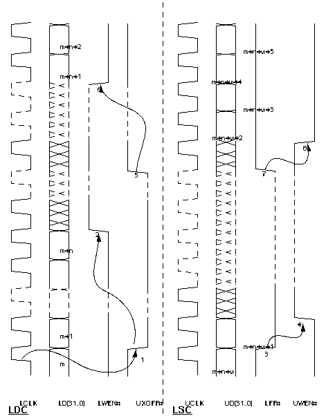
An example timing diagram is shown in Figure 4. In this diagram, the sequence of events is as follows;
1. The transfer of word m from the LDC to the ROMB causes the ROMB to set UXOFF# low. This is done asynchronously.
2. The LDC transmits an XOFF command back to the LSC. This causes the LSC to stop transmitting data. During the time taken for the XOFF command to travel back to the LSC, the LSC to respond and the last data word to be transmitted to the LDC, n additional words are received at the LDC.
3. At the LSC, data transmission stops with word m+n. The buffer fills after w more words are transferred and so LFF# is set low. In this case, one more word is transferred by the FEMB, although up to two words may be transferred. This is word m+n+w+1.
4. The FEMB does not transfer any more data to the LSC (UWEN# high).
5. At the LDC, no more data is being transferred to the ROMB so it has time to clear its buffer or process the data. After some time, it is ready to receive data again. To re-start the dataflow, the ROMB sets UXOFF# high.
6. On seeing UXOFF# go high, the LDC transmits an XON command back to the LSC. This causes the LSC begin transmitting data again. Again there is a delay while the XON command travels to the LSC, the LSC responds and the data travels up to the LDC. Eventually, the data arrives and the LDC sets LWEN# low to transfer it to the ROMB.
7. At the LSC, the buffer is cleared and so LFF# is set high.
8. The FEMB now can resume the transfer of data to the LSC and so sets UWEN# low. The re-established dataflow then continues until the end of data or a new XOFF state arises.
FIGURE 4. Flow Control: Sequence of Events