5.0 Physical Description
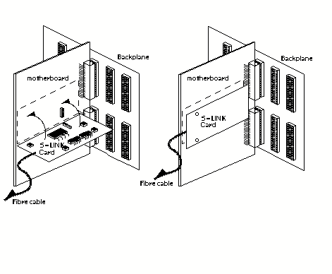
FIGURE 10. A representation of how an S-LINK card is mounted on a 6U VME motherboard.
1. The physical shape of the S-LINK card shall be as defined in Figure 11.
2. Signal I/O and power distribution to the S-LINK card shall be handled by a single connector, positioned outwith the set of CMC Standard positions, as shown in Figure 11.
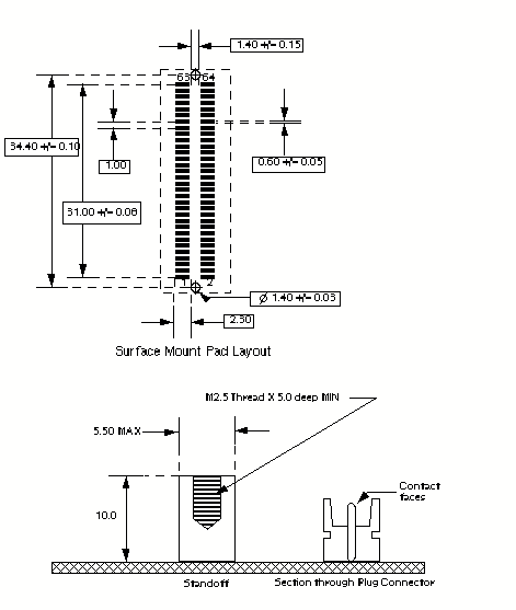
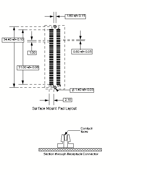
3. The connector is a 64-pin surface-mount CMC connector and is a plug on both S-LINK cards (LSC and LDC) and a receptacle on both motherboards (FEMB and ROMB). Drawings of the surface mount pad layouts for the connectors are given in Figure 12 and Figure 13.
FIGURE 12. CMC "P" Plug Connector on S-LINK card with standoff drawing
FIGURE 13. CMC "J" Receptacle Connector on motherboard 
4. S-LINK cards may function with either a +5.0 V or with a +3.3 V supply. The LSC and LDC shall be provided with a keying hole which defines which voltage the card requires. The motherboard shall provide the keying pin.
5. S-LINK cards shall be provided with a keying hole which defines whether the card is a LSC or a LDC. The motherboard shall provide the keying pin.
The arrangement of the keying pins is given in Table 16 and a technical drawing of a keying pin is given in Figure 14.
TABLE 16. Arrangement of Keying Pins
| Type of card | Voltage Pins | LSC/LDC Pins | ||
| Has Pin 1 | Has Hole 1 | Has Pin 2 | Has Hole 2 | |
| 5V FEMB | yes | yes | ||
| 3.3V FEMB | no | yes | ||
| 5V LSC | yes | yes | ||
| 3.3V LSC | no | yes | ||
| 5V ROMB | yes | no | ||
| 3.3V ROMB | no | no | ||
| 5V LDC | yes | no | ||
| 3.3V LDC | no | no |
6. The standoff pillars and the CMC bezel front panel are mounted on the S-LINK cards. The keying pins are mounted on the motherboard. To avoid ground loops and antenna effects, the standoff pillars, attachment areas, keying pins, keying holes and CMC bezel front-panel (if fitted) are to be grounded or isolated as described in Table 17 and Table 18.
The general rule is that each component is grounded with respect to the card on which it is mounted. Corresponding holes on the other card are then isolated. The only exception is the CMC bezel front panel which is completely isolated.
A drawing of a standoff pillar is given in Figure 12.
TABLE 17. Grounding considerations for FEMBs or ROMBs
| Standoff attachment area (screw hole) | isolate |
| Keying pin | ground |
TABLE 18. Grounding considerations for LSCs or LDCs
| Standoff pillar | ground |
| Keying hole | isolate |
| CMC bezel front-panel (if fitted) | isolate |